
航拍:绿杨烟外晓寒轻,桃李枝头春意闹

In digital electronics, a counter is a sequential logic circuit that counts and stores the number of positive or negative transitions of a clock signal.[1] A counter typically consists of flip-flops, which store a value representing the current count, and in many cases, additional logic to effect particular counting sequences, qualify clocks and perform other functions. Each relevant clock transition causes the value stored in the counter to increment or decrement (increase or decrease by one).
A digital counter is a finite state machine,[2] with a clock input signal and multiple output signals that collectively represent the state. The state indicates the current count, encoded directly as a binary or binary-coded decimal (BCD) number or using encodings such as one-hot or Gray code. Most counters have a reset input which is used to initialize the count. Depending on the design, a counter may have additional inputs to control functions such as count enabling and parallel data loading.
Digital counters are categorized in various ways, including by attributes such as modulus and output encoding, and by supplemental capabilities such as data preloading and bidirectional (up and down) counting. Every counter is classified as either synchronous or asynchronous. Some counters, specifically ring counters and Johnson counters, are categorized according to their unique architectures.
Counters are the most commonly used sequential circuits[2] and are widely used in computers, measurement and control, device interfaces, and other applications. They are implemented as stand-alone integrated circuits and as components of larger integrated circuits such as microcontrollers and FPGAs.
Characteristics
[edit]An electronic counter is a sequential logic circuit that has a clock input signal and a group of output signals that represent an integer "count" value. Upon each qualified clock edge, the circuit will increment (or decrement, depending on circuit design) the stored count. When the count reaches the end of the counting sequence (maximum count when incrementing; zero count when decrementing), the next clock will cause the count to overflow or underflow and the counting sequence will start over.
Signals
[edit]
Every counter has a fundamental group of signals common to state machines:
- Clock (input) - triggers state change upon rising or falling edge (known as the active edge[3]).
- Reset (input) – sets count to zero. Some IC manufacturers name this signal "clear" or "master reset (MR)". Depending on the counter design, this signal may be asynchronous or synchronous.
- Count (output) - bit vector representing the accumulated count. Depending on the counter design, this may be the current state (flip-flop outputs) or an encoding of the current state.
In addition to Clock and Reset, many counters provide other input signals such as:
- Enable – allows or inhibits counting. Sometimes this is labeled CE (count enable).
- Direction – determines whether count will increment or decrement.
- Data – parallel input data which represents a particular count value.
- Load – copies parallel input data to the counter. This typically takes precedence over Enable if both Load and Enable are asserted.[2]
Counter inputs are in many cases synchronous, meaning that they only affect counter operation upon active clock edges. For any particular counter, each synchronous input signal must satisfy the setup and hold times required for proper operation (i.e., it must be stable before and after every active clock edge for specified minimum times).[3]
Some counters provide a Terminal Count output which indicates that the next clock will cause overflow or underflow. This is used in various ways, including:
- to implement counter cascading (combining two or more counters to create a single, larger counter) by connecting the Terminal Count output of one counter to the Enable input of the next counter.
- to change the counter modulus, by connecting Terminal Count to the counter’s Load input and applying an appropriate value to the Data inputs.
Output encoding
[edit]As it counts, every counter produces a sequence of output codes (bit patterns) on its Count outputs. Many of these code sequences, either by design or due to the nature of the counter, conform to widely used encoding systems. Several types of output encoding are commonly used in counters, including binary, BCD, Gray code, and one-hot.
Modulus
[edit]The modulus of a counter is the number of states in its count sequence.[2] A counter that has modulus value m is commonly referred to as a modulo-m or MOD-m counter. For example, a decade counter is a digital counter which has ten states, and therefore is a MOD-10 counter.[4]
The maximum possible modulus of a counter is determined by the number of flip-flops. More specifically, a counter with n flip-flops has a maximum possible modulus of 2n.[4] For example, a four-bit counter can have a modulus of up to 16 (24).
Some counters (e.g., binary counters) include all possible states in their count sequences. Other counters omit one or more possible states from their counting sequences. For example, a MOD-10 (decade) counter with four flip-flops only uses ten of 16 possible states.
Clocking method
[edit]Counters are broadly categorized as either synchronous or asynchronous depending on whether their flip-flops are clocked simultaneously or at different times.
Synchronous
[edit]In synchronous counters, all flip-flops share a common clock and change states at the same time.[3]
Asynchronous (ripple)
[edit]In an asynchronous counter, also known as a ripple counter,[4] each flip-flop has a unique clock. The flip-flops are arranged in a "chain", with the counter's input clock connected to the first flip-flop and the output of each flip-flop clocking the next flip-flop in the chain. The natural counting sequence of such circuits is binary, and consequently most asynchronous counters are binary, with each flip-flop storing one bit of the binary count value.[5]
Since every flip-flop introduces a delay from active clock edge to output toggle, the counter bits change state at different times, producing a ripple effect that causes the count to be unstable while the input clock propagates through the flip-flops. During this instablility, the count will briefly transition through one or more invalid values. The duration of this instability (the settling time) depends on several factors, including the clock-to-output delay for each flip-flop and, for any particular count transition, the number of bits that change state. The maximum settling time occurs when all the counter bits change state (i.e., when the counter overflows or underflows) and thus is proportional to the number of flip-flops.
This makes ripple counters unsuitable for use in synchronous circuits that require the counter to have a fast output settling time.[6] Also, it is often impractical to use ripple counter output bits as clocks for external circuits because the ripple effect causes timing skew between the bits. Ripple counters are commonly used as general-purpose counters and clock frequency dividers in applications where the instantaneous count and timing skew is unimportant. Asynchronous counters are typically not used in VLSI ICs due to the difficulties of simulating and testing them and because they require much greater design effort to ensure reliable operation.[3]
Count direction
[edit]Many counters are designed to count in only one direction, meaning that they will either count up or down, but not both. A counter that only counts up is typically referred to as an up-counter, and one that only counts down as a down-counter.[6]
A bidirectional counter or up/down counter is a digital counter which counts up or down as directed by a direction control input signal. In synchronous up/down counters, the control signal is a single digital input whose state indicates count direction (e.g., '1' = count up; '0' = count down). In asynchronous up/down counters the direction control may alternatively consist of separate "up" and "down" clock inputs.
Common types
[edit]Binary counter
[edit]A binary counter is a digital counter that directly represents the count as a binary number. A binary counter is a MOD-2n counter, where n is the number of flip-flops used to store the count. For example, the illustrations below show the behavior of a 5-bit binary counter, which has 32 (25) states and is therefore a MOD-32 counter:
-
 Count sequence of a 5-bit binary up-counter
 -
 Voltage changes on the outputs of a 5-bit binary counter as it counts up from 0 to 31 (left to right), with most-significant bit on top row and successively less-significant bits in the rows below


Asynchronous binary counter
[edit]An asynchronous binary counter, or binary ripple counter, is a "chain" of toggle (T) flip-flops (or equivalent) in which the least-significant flip-flop (bit 0) is clocked by the counter input clock, and all other flip-flops are clocked by the output of the nearest, less significant flip-flop (e.g., bit 0 clocks bit 1 flip-flop, bit 1 clocks bit 2, etc.). When implemented with JK or D flip-flops, each flip-flop is configured to toggle when clocked (i.e., J and K connected to logic high; D connected to Q).
-
 Schematic diagram of an n-bit ripple counter constructed from JK flip flops. In this counter, the first flip-flop is clocked by rising edges; all other flip-flops are clocked by falling edges.
 -
 Timing diagram of a 4-bit binary ripple counter during overflow, illustrating how the normal counting sequence is violated while the input clock propagates through the counter circuitry


Each flip-flop is effectively a one-bit counter which increments its count (by toggling its output) once per clock cycle. It counts from zero to one and then, when the next clock arrives, it will overflow and start its count sequence over again at zero. Each output state persists for a full input clock cycle, and consequently the frequency of each flip-flop's output signal is exactly half that of its input clock. Additional flip-flops may be added to the chain to form a counter of any arbitrary word size (number of bits), with the output frequency of each bit equal to exactly half the frequency of its nearest, less significant bit.
-
 Functional diagram of a CMOS 4020, 14-bit ripple counter IC
 -
 Photograph of a CMOS 4020, 14-bit ripple counter IC (RCA CD74HC4020E)


Synchronous binary counter
[edit]The circuit shown below is a synchronous, up-counting four-bit binary counter implemented with JK flip-flops. Upon clock rising edge, bit 0 will always toggle, whereas other bits will toggle only when all less-significant bits are at a logic high state (i.e., Q1 toggles if Q0 is logic high; Q2 toggles if Q0 and Q1 are both high; and Q3 toggles if Q0, Q1, and Q2 are all high).

As in asynchronous counters, each flip-flop introduces a delay from input clock edge to output toggle, but in this case all flip-flops change state concurrently, and consequently the counter output will settle after only one flip-flop delay regardless of the number of bits.
BCD decade counter
[edit]A binary-coded decimal (BCD) decade counter is a MOD-10 counter that directly represents the count as a binary number in the range 0 to 9. Typically a BCD decade counter will count up from 0 to 9 and then overflow. Because their output value range is identical to that of a decimal digit, BCD decade counters are commonly used to represent decimal digits.
| BCD decade counter output states | ||||
|---|---|---|---|---|
| State | Q0 | Q1 | Q2 | Q3 |
| 0 | 0 | 0 | 0 | 0 |
| 1 | 1 | 0 | 0 | 0 |
| 2 | 0 | 1 | 0 | 0 |
| 3 | 1 | 1 | 0 | 0 |
| 4 | 0 | 0 | 1 | 0 |
| 5 | 1 | 0 | 1 | 0 |
| 6 | 0 | 1 | 1 | 0 |
| 7 | 1 | 1 | 1 | 0 |
| 8 | 0 | 0 | 0 | 1 |
| 9 | 1 | 0 | 0 | 1 |
Asynchronous BCD decade counter
[edit]The circuit shown below is an asynchronous BCD decade counter. It is effectively a 4-bit binary ripple counter that uses an AND gate to reset the count to zero (by resetting all flip-flops) when the binary count increments to decimal 10 (binary 1010), thus resulting in 10 output states. As in all asynchronous counters, the stored count is unstable while the external clock propagates through the flip-flop chain (including the reset upon reaching count 10).
-
 Schematic diagram of a 4-bit asynchronous BCD decade counter constructed from toggle flip-flops
 -
 Timing diagram of a 4-bit asynchronous BCD decade counter during overflow, illustrating how the output passes through invalid states as the count transitions from decimal 9 to 0


Synchronous BCD decade counter
[edit]The circuit shown below is a synchronous BCD decade counter. Five logic gates are used to implement the next-state logic, thus facilitating faster operation than an asynchronous counter at the expense of additional circuitry.

Ring counter
[edit]A ring counter is a circular shift register which is initialized (via its reset input signal) such that one flip-flop (typically bit 0) stores a ‘1’ and all other flip-flops store a ‘0’. Each clock pulse causes the ‘1’ to shift to the next flip-flop. When the ‘1’ reaches the last flip-flop in the shift register, the next clock causes it to shift into the first flip-flop, thus restarting the counting sequence and effecting a counter overflow. At any particular time only one counter output bit is logic ‘1’, and consequently a ring counter is effectively a one-hot state machine.
A ring counter is MOD-n, where n is the number of flip-flops. For example, the ring counter shown below has four flip-flops and therefore is a MOD-4 counter. In this counter, bit 0 is initially set and all other bits are cleared.

| 4-bit ring counter output states | ||||
|---|---|---|---|---|
| Count | Q0 | Q1 | Q2 | Q3 |
| 0 | 1 | 0 | 0 | 0 |
| 1 | 0 | 1 | 0 | 0 |
| 2 | 0 | 0 | 1 | 0 |
| 3 | 0 | 0 | 0 | 1 |
Johnson counter
[edit]A Johnson counter is a circular shift register in which the output of the last stage is inverted and connected to the data input of the first stage,[7][8][9] and all bits are initialized to zero, thus producing a Gray code output sequence. It can be clocked at relatively high frequencies because there are no intermediate logic gates, and consequently the worst-case propagation delay is from clock to flip-flop output. A Johnson counter is MOD-2n, where n is the number of flip-flops. For example, the Johnson counter shown below has four flip-flops and therefore is a MOD-8 counter.

| 4-bit Johnson counter output states | ||||
|---|---|---|---|---|
| State | Q0 | Q1 | Q2 | Q3 |
| 0 | 0 | 0 | 0 | 0 |
| 1 | 1 | 0 | 0 | 0 |
| 2 | 1 | 1 | 0 | 0 |
| 3 | 1 | 1 | 1 | 0 |
| 4 | 1 | 1 | 1 | 1 |
| 5 | 0 | 1 | 1 | 1 |
| 6 | 0 | 0 | 1 | 1 |
| 7 | 0 | 0 | 0 | 1 |
Johnson counters are commonly used in state machines and in specialized applications such as analog waveform generation (e.g., Davies sinusoidal generator).[10]
State machine attributes
[edit]State register
[edit]A digital counter is a finite state machine in which the counter's flip-flops serve as the state register. The value stored in the state register is a bit vector comprising the counter's current state.
State sequencing
[edit]When not otherwise influenced by its input signals, a counter will cyclically step through a fixed sequence of states.[2] Consequently, the state diagram for a counter has the appearance of a loop. For example, a MOD-8 counter will repeatedly loop through eight states:
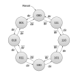
- State diagrams of various MOD-8 counters
-
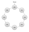 Basic 3-bit binary up-counter
 -
 3-bit bidirectional binary counter. Count direction is controlled by dir input: 1=up, 0=down.
 -
 3-bit binary up-counter with Count Enable (CE) input
 -
 4-bit Johnson counter
 -
 8-bit ring counter


Illegal states
[edit]
A counter having flip-flops and modulus uses only a fraction of its possible states. The unused states are typically referred to as illegal states,[2] as they are forbidden during normal operation. In general, a MOD- counter with flip-flops has illegal states. For example, a MOD-10 BCD decade counter with four flip-flops has six () illegal states. A Johnson counter has , and a ring counter has illegal states.


During normal operation, a counter will never enter an illegal state. However, in some cases it is possible for a glitch (e.g., due to power supply noise, radiation exposure) to cause a counter to erroneously enter an illegal state. To allow for this possibility, counters are often designed to automatically recover from illegal states by transitioning to a valid state.
General model
[edit]Digital counters are typically implemented as Moore machines because their outputs are determined solely by the current state.[11] This makes counters a natural fit for Moore machines, which in turn simplifies the design and promotes reliable operation.[1]
More specifically, counters are most commonly implemented as Medvedev state machines, a subclass of Moore machines which directly output the current state, with each state naturally encoding a specific count value.[12] Since the state register of such machines is directly connected to the counter outputs, encoding logic is not needed and output delays are minimized.


Some counters employ combinational logic between state register and counter outputs to transform the state to a particular output encoding, and thus are classified as full Moore machines. For example, the CMOS 4017 integrated circuit encodes the output of a Johnson decade counter into one-hot format, taking advantage of the Johnson counter's inherent Gray code output to avoid glitches on the one-hot outputs.
-
 Functional diagram of a CMOS 4017 IC, which combines a 5-bit Johnson counter and output decoder logic to implement a cascadable one-hot decade counter
 -
 Internal logic of a CMOS 4017 IC; one output is active per state. The two gates at the top facilitate automatic recovery from illegal states.


Implementation
[edit]Counters are implemented in a variety of ways, including as dedicated MSI and LSI integrated circuits, as embedded counters within ASICs, as general-purpose counter and timer peripherals in microcontrollers, and as IP blocks in FPGAs. In the latter case, a counter is typically instantiated by synthesizing it from a description written in VHDL, Verilog or some other hardware description language. For example, the following VHDL code describes a 32-bit binary up/down counter with count enable and preload capability:
entity bidirectional_counter is
port (                                      -- counter input/output signals:
  CLK         : in  std_logic;              --   clock
  RESET       : in  std_logic;              --   asynchronous reset
  ENABLE      : in  std_logic;              --   count enable
  LOAD_ENABLE : in  std_logic;              --   load enable
  COUNT_UP    : in  std_logic;              --   '1' for up, '0' for down counting
  DATA_IN     : in  unsigned(31 downto 0);  --   value to load into counter
  DATA_OUT    : out unsigned(31 downto 0)   --   current counter value
);
end bidirectional_counter;

architecture behavioral of bidirectional_counter is
  signal counter : unsigned(31 downto 0) := (others => '0'); -- counter register
begin
  process(CLK, RESET)
  begin
    if RESET = '1' then             -- if counter reset is requested
      counter <= (others => '0');   --   reset the counter
    elsif rising_edge(CLK) then     -- else upon rising clock edge
      if LOAD_ENABLE = '1' then     --   if load is requested
        counter <= DATA_IN;         --     jam new value into counter
      elsif ENABLE = '0' then       --   else if counting is disabled
        null;                       --     do nothing
      elsif COUNT_UP = '1' then     --   else if up-counting
        counter <= counter + 1;     --     increment counter
      else                          --   else down-counting, so
        counter <= counter - 1;     --     decrement counter
      end if;
    end if;
  end process;
  DATA_OUT <= counter;    -- output current counter value
end behavioral;
In MSI and LSI integrated circuits, a counter is implemented as a semiconductor die which is bonded and encapsulated in a semiconductor package.
-
 Semiconductor die of a synchronous 4-bit binary counter
 -
 Assembled synchronous 4-bit binary counter in a plastic dual-in-line package


Cascading
[edit]Some counters are cascadable, meaning that multiple instances of such counters can be connected together to form a larger, extended counter with a greater modulus. To facilitate cascading, a cascadable counter typically has an enable input that enables counting, and an output that propagates overflows or underflows to the enable input of the next counter in the cascade.[2]
The first (least-significant) counter in a cascade may be permanently enabled by connecting its enable input to a fixed logic level, or its enable input may be dynamically driven. In either case, the enable input of the first counter serves as a count enable for the entire extended counter.
Cascadable binary counters typically output a ripple-carry signal to notify the next counter in the cascade of an impending overflow or underflow. For example, in the four-bit cascadable up-counter shown below, an AND gate asserts the ripple-carry output (RCO) when the next clock is expected to cause an overflow (I.e., when the count is binary 1111 and counting is enabled):
-
 Cascadable 4-bit binary up-counter
 -
 A cascade of 4-bit binary up-counters used to implement an n-bit up-counter, where n is a multiple of four


Applications
[edit]Binary counters are widely used as timers and event counters.
In a digital timer, the counter is clocked by a periodic digital signal which serves as a time reference and causes the count to change at a constant rate. The clock signal is typically sourced by a stable frequency source such as a crystal oscillator, either directly or via a clock divider. Depending on the application, a timer may output a signal that indicates timing status, or it may output the current count, or both. In the latter case, the count typically indicates either the elapsed or remaining time.
Event counters are typically used to count asynchronous events that may or may not occur at variable frequencies. At any particular time, the current count indicates the number of events that have occurred since event counting began.
Memory addressing
[edit]Binary counters are used extensively in computers to generate memory addresses. In such applications, the counter output is typically connected to an address bus and used to sequentially select contiguous memory locations as the count increments or decrements. Widespread examples of this include program counters, direct memory access (DMA) controllers, and FIFO buffers. When used to hold data addresses during data transfer operations, a counter is commonly referred to as a memory address register (MAR).[13][14]
Program counter
[edit]The program counter (PC) in a central processing unit typically consists of a binary counter as shown in the following example:

In the above PC, the current count is the memory address of the next instruction to be executed. Upon processor reset, the count is zeroed so that execution will begin at address zero. When an instruction is fetched from memory, CE (count enable) is asserted to allow the counter to increment the count and thus advance to the next sequential instruction address. If it becomes necessary to switch execution to a different instruction sequence (e.g., due to executing a branch instruction, subroutine call, interrupt, or return from subroutine or interrupt), the address of the first instruction in the new sequence is applied to the Data inputs and Load is asserted; this overrides CE (if asserted) and copies Data to Count.
FIFO
[edit]Electronic FIFO (First-In, First-Out) buffers are commonly used to interface data producing devices to data consumers that operate in different clock domains or which, over finite intervals, cannot consume data fast enough to avoid data loss.
The FIFO shown below employs two binary counters as memory address registers (MARs) for a dual-port RAM. Upon FIFO write, data word WDATA is written to RAM address WADDR and the Write MAR is incremented to prepare for the next write. Upon FIFO read, RDATA receives the data word stored at RAM address RADDR and the Read MAR is incremented. Except for the special case when the FIFO is full, the FIFO level (number of unread words in the FIFO) is equal to WADDR-RADDR.

This FIFO may be asynchronous or synchronous, meaning that read and write operations may take place in different clock domains or in a single, common clock domain, respectively. In the latter case, RCLK and WCLK are connected together.
DMA controller
[edit]Binary counters are used in various ways in direct memory access (DMA) controllers. For example, counters similar to those shown below are utilized when copying a memory buffer via DMA. Two counters are employed as memory address registers (MARs) to generate source and destination addresses for the data to be copied. The MARs are typically bidirectional to allow data transfers to begin at the base or end address of a buffer. A third counter keeps track of the number of remaining words to be transferred.


To prepare for the DMA operation, the initial addresses are loaded into the MARs, the buffer size is loaded into the data transfer counter, and the count direction (typically stored in a flip-flop) is programmed for each MAR.
When each word transfer completes, CE (count enable) is asserted on all counters, thus causing the MARs to advance to their next address and the remaining word count to decrement. When the remaining count reaches zero, the logic NOR of its bits switches high, thus signaling that the DMA operation has completed.
One-shot timer
[edit]In digital electronics, a one-shot timer (or simply one-shot) is a circuit that produces a single, precisely timed output pulse in response to an input trigger. The digital design allows for easy adjustment of pulse duration and provides high accuracy and repeatability compared to analog counterparts, making digital one-shots preferable for applications where timing accuracy is critical.[15]
The one-shot timer shown below uses a binary down-counter to generate an output pulse of precisely controlled duration. The timer output is the logical OR of all bits in the current count, and consequently the output pulse is active while the timer is running (I.e., when the count is not zero). When the count reaches zero, the output pulse is terminated and counting is halted.

To start the timer running, a value representing the desired pulse width is applied to the counter's Data inputs and Load is asserted to trigger pulse generation. The pulse width is specified in terms of clock cycles. For example, in the case of a 1 MHz clock, a 100 microsecond output pulse has a duration of 100 clock cycles, as shown below:

The one-shot shown above is retriggerable, meaning that it can be restarted by a subsequent trigger while running and thus stretch (extend the duration of) the output pulse. Conversely, the one-shot shown below is non-retriggerable, meaning that it will ignore incoming triggers while the output pulse is active.

Periodic interval timer
[edit]Binary counters are commonly used as periodic interval timers (PITs), which output periodic pulses at an integer fraction of the clock frequency. PITs are used to generate system clock interrupts in computers, as clock dividers in phase lock loops and frequency synthesizers, and in many other applications.
In the circuit below, a binary down-counter is used to implement a PIT. The interval between output pulses, measured in clock cycles, is stored in the Interval register, resulting in output frequency . When the count reaches zero, the NOR gate issues a pulse on the timer output. The output pulse is also used internally to reload the interval into the counter, thus restarting the timer. Each output pulse has a duration of one clock cycle.


For example, to obtain a 1 MHz output frequency from a 6 MHz clock, the interval would be set to 5 as shown in the following timing diagram:

Pulse width modulator
[edit]Binary counters are an essential building block in digital pulse width modulators, which are commonly used to control motor speed, temperature, LED brightness, and other physical processes. These can be implemented in various ways. For example, the pulse width modulator shown below uses a single binary up-counter with synchronous reset to control both the width and frequency of output pulses:

The value stored in the PWM period register () determines the output frequency. increments at clock frequency until it matches , which causes the identity comparator to strobe EndCycle, thus resetting the counter and starting the next output cycle. Consequently, the counter modulus is and the output pulse frequency .


specifies the output pulse width in clock periods. The magnitude comparator asserts while Count is less than , thus producing a pulse that starts at the beginning of the output cycle and ends when the count reaches . A flip-flop buffers to prevent glitches from appearing on the PWM output.


The duty cycle is the percentage of PWM cycle time in which the pulse is active: . For example, the following diagram shows signal timing for and , resulting in a 25 percent duty cycle at Hertz.


Pulse width measurement
[edit]Pulse width measurement is a common counter application that is used in a wide variety of equipment, including radar and sonar, industrial automation, and medical imaging systems. A typical circuit is shown below, which uses a binary up-counter to measure the widths of asynchronous (with respect to the counter clock) positive pulses.

The measured signal is first synchronized to the counter's clock domain, thus producing the synchronized input signal Clock gate. This is done to prevent measurement errors due to metastability or violations of minimum setup or hold times in the counter and edge detector flip-flops.
When a Clock gate pulse begins, the rising edge detector strobes Start to zero the count, and the counter then proceeds to count clock pulses while Clock gate remains active. When the pulse ends, the counter stops counting and the accumulated count indicates the measured pulse width in units of clock periods. The pulse width is seconds, where is the clock frequency in Hertz.

A falling edge detector strobes End to indicate end of measurement, which can be used to signal external circuitry or transfer the count to external storage, or both, before the next measurement begins.
Frequency counter
[edit]Some counter applications utilize multiple counters. An example of this is the frequency counter shown below, which uses two counters to measure the frequency of a digital signal. One counter, configured as a one-shot, produces a pulse of precisely controlled width known as the time gate. The time gate is used to enable the clocking of an event counter, which is clocked by the signal whose frequency is to be measured.

When a measurement begins (by asserting Start), the event counter is zeroed and then proceeds to count rising edges of the unknown frequency signal while the time gate remains active. When the time gate ends, edge counting stops and the accumulated count indicates the measured frequency. The count directly indicates the measured frequency in Hz when the gate time is one second; for other gate times, the count must be scaled to obtain Hz.
Analog-to-digital conversion
[edit]Counters are employed in various ways in analog-to-digital converter (ADC) circuits. For example, in a tracking ADC, a bidirectional binary counter is used to control the output voltage () of a digital-to-analog converter. is proportional to the count and thus increases or decreases, respectively, when the count is incremented or decremented.

![]()
A voltage comparator outputs a bit indicating whether is greater than ADC input voltage . This bit controls the count direction such that the count — and DAC voltage — will increase or decrease, respectively, when the is less than or greater than , thus causing to track . Since the count tracks in near real time, it is directly used as ADC output data.

Position tracking
[edit]Bidirectional binary counters are commonly used to track the physical position of moving objects that are monitored by incremental encoders, as shown in the example circuit below. A position change is indicated by a rising or falling edge on the encoder's A or B output signal. Each position change is associated with a well-defined distance , with the phase difference between A and B indicating the direction of travel (e.g., "forward" or "reverse"). The count is incremented or decremented when the object moves in the forward or reverse direction, respectively.


To begin tracking, the monitored object is located at a reference position () and the count is zeroed. From that point on, the count indicates the current position in terms of displacement from the reference position, measured in distance units: . The count is effectively a signed integer in cases where the object can move to either side of the reference position.


Stepped sinusoidal waveform generator
[edit]A sinusoidal voltage waveform can be approximated by cycling through the output states of a Johnson counter and summing the output voltages through a network of resistors which are weighted to map each counter state to a point in the cosine function:[10]

The resulting sinusoidal waveform has frequency for flip-flops and a clock frequency of . Consequently, the sine wave frequency can be changed simply by changing the clock frequency.


Harmonic distortion is reduced by increasing , which gives more steps and smaller step sizes in the sine wave; by increasing resistance accuracy; and by adding a capacitor or active filter to low-pass filter the edges of voltage steps.


See also
[edit]References
[edit]- ^ a b Mano, M. Morris; Ciletti, Michael D. (2012). Digital Design (5th ed.). Prentice Hall. ISBN 0132774208.
- ^ a b c d e f g "Registered Logic Design" (PDF). Advanced Micro Devices. 1996. Retrieved 9 May 2025.
- ^ a b c d Keslin, Hubert (2014). Top-down Digital VLSI Design: From Architectures to Gate-Level Circuits and FPGAs. Morgan Kaufmann. ISBN 0128007729.
- ^ a b c Maini, Anil K. (2007). Digital Electronics: Principles, Devices and Applications (PDF). John Wiley & Sons, Ltd. ISBN 978-0-470-03214-5. Retrieved 1 May 2025.
- ^ Mano, Morris. Digital Logic and Computer Design (1st ed.). Pearson. ISBN 978-0132145107.
- ^ a b Gorla, Raju. "Counters - Digital Circuits". VLSI Web. Retrieved 9 May 2025.
- ^ Singh, Arun Kumar (2006). Digital Principles Foundation of Circuit Design and Application. New Age Publishers. ISBN 81-224-1759-0.
- ^ Horowitz, Paul; Hill, Winfield (1989). The Art of Electronics. Cambridge University Press. ISBN 0-521-37095-7.
- ^ Graf, Rudolf F (1999). Modern Dictionary of Electronics. Newnes. ISBN 0-7506-9866-7.
- ^ a b Dunbar, Steven. "The Davies Sinusoidal Generator" (PDF). Texas Instruments. Retrieved 27 March 2025.
- ^ Mano, M. Morris; Kime, Charles R. (2007). Logic and Computer Design Fundamentals. Prentice Hall. ISBN 978-0131989269.
- ^ a b Khoussainov; Nerode (2001). Automata Theory and its Applications. Springer. ISBN 978-0-8176-4207-5.
- ^ Stallings, William (2012). Computer Organization and Architecture (9th ed.). Pearson. ISBN 978-0132936330.
- ^ Harris, David; Harris, Sarah (2012). Digital Design and Computer Architecture (2nd ed.). Morgan Kaufmann. ISBN 978-0123838728.
- ^ Sidney, M. (2014). Digital Electronics and Logic Design. McGraw-Hill. ISBN 978-9351640936.
External links
[edit] Media related to Counter circuits at Wikimedia Commons
- Assim, Ara Abdulsatar Assim (2025-08-06). Design and Synthesis of a MOD 13 Binary Down Counter (Report). doi:10.36227/techrxiv.16810198.v1.